
-
-
-
-
-
About Stropower

-

——
Solution
Time Accuracy & Control Speed - Making Differences between Test Abilities
Details will make a difference – How the time accuracy for your Battery cycling test matters
There are many compulsory limits for the equipment or metering units’ tolerance for battery testing, typically example for the voltage, current and temperature, which could be and actually generally adopted by industries where heavy battery dependence lies in.
It is like this because of the qualification standards has clear depiction and the deviation from this is easy to be predicted since these are really key factors for batteries’ performance and functionality; however, another important side effect to form this common sense is actually because of – we can agree on how to explain these tolerances.
For instance, when an auto company wants to test its battery’s capacity, what must be agreed between his battery supplier and him is that the tolerance should be guaranteed not been passing over. We should make sure the current gage during the test can be reliable to support this proofing test, because tested capacity data is no more than the integral result of current over the test period. Here, everything is clear enough for a commercial contract on the current tolerance limit, and it’s clear not only by its meaning but also that there are several universally defined calibration methods to take for guaranteed, for example of Hall sensor method or current sharing method, Roche coil way or active differential probe way.
Although most of the physical parameters are generally clear from standards (either as IEC 62660 or GB/T 31486 or countless else), still one is left behind from actual effectiveness and that is “time tolerance”.
What does it mean when it appears like “±0.1%” or “±0.1s” for the “time” during tests of batteries ? It is hard to say, since maybe you will get different answers after different responsibility persons or thinking owners, and there is barely any common understanding to make it “clear”.
Relating to what we had acknowledged during the long past user experience, we think the most important and time-sensitive measurements in terms of power battery for EVs or other kinds of auto mobile powertrain applications, will be pulse tests: the most common scenario is current or power defined profile tracking tests – to simulate the instantaneous response behavior performance in order to either verify the cycle aging or power response speed.
Starting from this we have really proven examples for how time tolerance matters regarding to battery cycling and power response – the delay of response is the reciprocal side of where time tolerance impacts a lot and should be verified or leveraged up for reasonably correct or even test requirements.
It is very clear that slow response to current or power call during conventional “CC”
or “CV” test would be obviously identified from multimeter units or data log. And the long run of cycles gives a none negligible deviation to test programs. A simple example of the affect is over charging or discharging – because of the switching or response delay leads to cumulative “small” abusing loads to battery under test.
Here is an engineering proposal from Stropower to its concerning customers and users on an easy and applicable method to verify so called “time tolerance”. The reference battery type can be uniformed to some specific models to contain the difference brought by DUT difference. Then the test for measuring time tolerance is performed by a 10 mins cycling sequencies containing 60 cycles of 10 second charging-discharging phases. The final tolerance is measured through the actual finishing time duration deducted by standard test commands (10 mins).
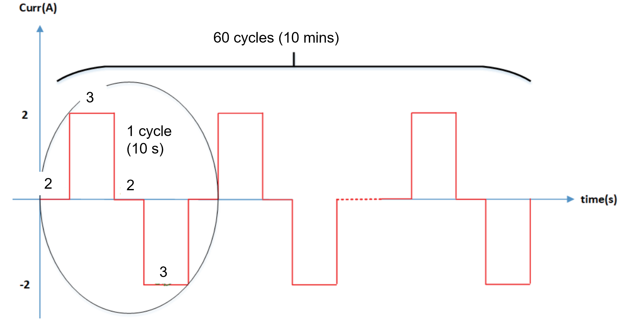
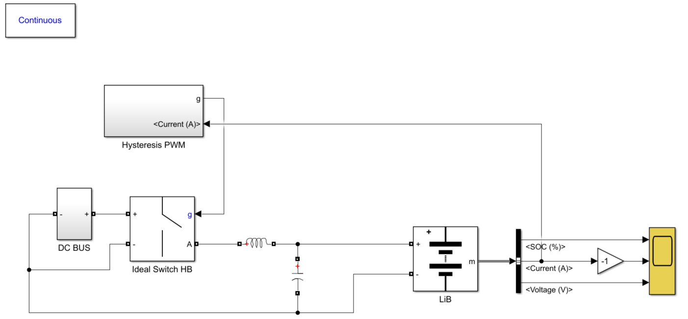
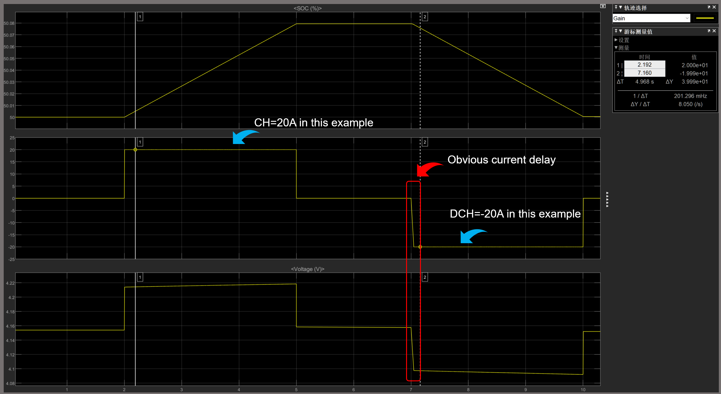
A simple simulation for this working profile as below: A hysteresis PWM Half-bridge charging – discharging loop is used according to “CC” demand. As we can see ever since the first cycle there is already small delay to test profile (literally no delay). Please attention that there is even no PID closed-loop control(which normally takes longer time) and most of the components are close to ideal.
Normally, based on today’s main battery cyclers’ technology used for control and measurement and conventional fast switching power discrete electronics, the delay to test demands or profiles will not obviously affect the battery capacity result because of the deviation during one cycle could not sum up enough high. However, it is another story when talking about long cycles and long term cycling, pro-longed high power charging and discharging eventually result in worse battery service life and SOH.
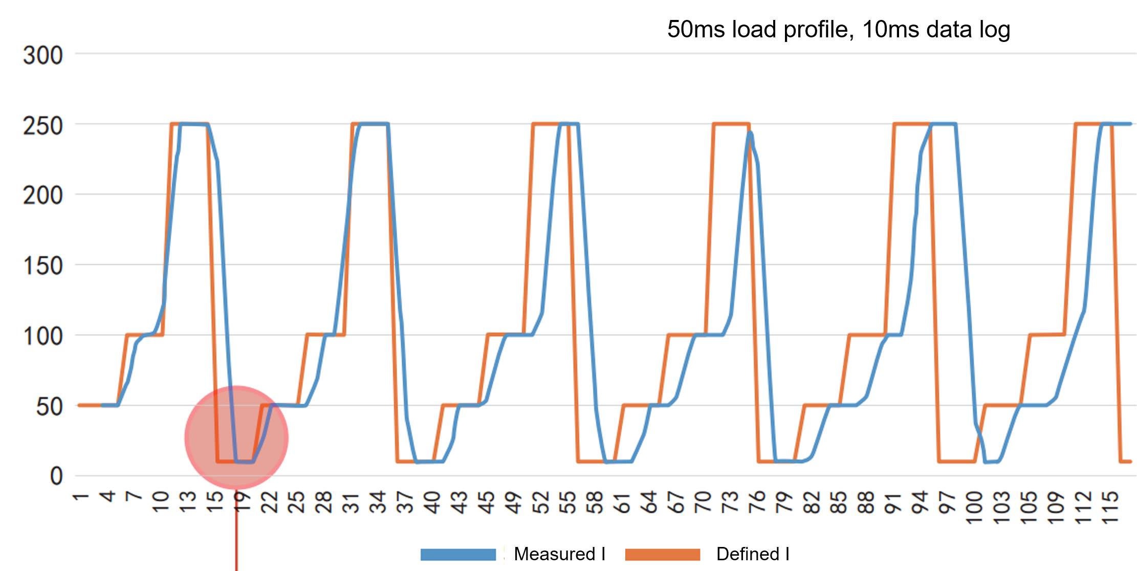
Nevertheless, there is one more instant adverse consequence from measuring the Ri of a battery, especially when SoC% is low. The Ri measurement are usually performed over an time interval of 100ms and typically for some worst cases the time delay of cutting off current or boost to target level lies in 1~10ms, and when SoC% is low the power response time of charging and discharging cycler takes even longer because of a larger voltage difference between DC bus and DUT.


2nd Floor, Building 3, East Zone, Modern Enterprise Center, No.2 Zhangba Wu Road, Yanta District, Xi 'an, Shaanxi